From fairest Sevens we desire increase
That thereby beauty's rose might never die,
And so it is with mildest caprice
That on a Duratec alights the eye.
That thereby beauty's rose might never die,
And so it is with mildest caprice
That on a Duratec alights the eye.
W. Shakespeare. Sonnet No. I (Unpublished variation)
A Beginning, a Muddle, and an End
Or Duratecs for Dummies (by a Dummy)
Or Duratecs for Dummies (by a Dummy)
Contents
I suppose I ought to start by saying that this write-up in no way constitutes an attempt on my part to set myself up as some sort of expert on Caterham Duratec conversions: as will become apparent if you read on, I am not, nor, I suspect, will I ever be. What it is intended to be is a mildly entertaining account of my Duratec conversion with, I hope, the fringe benefit of one or two useful pieces of information scattered within it. So, caveat lector or, more succinctly, "Fore!".
A short, short time ago in a place pretty close, an idle telephone call to a fine and generous gentleman (and no mean engine-builder) named John Howe (JH) resulted in a trip over to the 'Pit Lane' to see all the shiny bits he was amassing as he embarked on a no-holds-barred Duratec conversion.
"And I'm looking for a guinea pig for a low budget conversion" JH remarked at one point.
A good upbringing and a courteous nature meant that I greeted the remark with polite interest rather than an abrupt "Well you can stop looking at me as if I'm the offspring of a hippie rabbit and a gerbil!".
From that point onwards, my fate was sealed. I'm weak, I know, but what could I do?
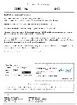
The following weeks were punctuated by e-mails from JH with subject lines such as "Engine for you" and containing links to advertisements for Duratec engines in various states. One engine was noticeably cheaper (sorry, better value) than most others. The advert is below. As it states, the engine had run in a Lotus Elise for 25 000 miles at which point it had started to sound a bit wrong. The engine had been stripped and it was found that the timing had slipped slightly and the valves had just touched the pistons very lightly. It was for this reason that new valves and pistons were used - see below.
I called the number.
"I'm on the bog - can you call back in 15 minutes."
An auspicious start. At least he won't be full of ... No, let's not bother.
I offered up the silent supplication
Oh Cloaca, goddess of that place,
Accept his offerings with good grace.
Smooth and consistent may they flow,
Neither rashly swift nor insolently slow
and called him back. Richard turned out to be a very pleasant and frank chap and to cut a long story s., Easter Sunday saw JH and me in the snow-blanketed car park of a hotel near Brands Hatch looking at the bits that can be seen below.


10 minutes later I was £380 poorer (but oh how much richer in spirit?) and heading back up the M20. The tintop appeared to be making an almighty row, but I quickly traced the source of the noise to JH who was berating me in no uncertain manner for having paid too much: "You f***ing useless numpty - he'd have taken £350 and I'd have got it for £300. How am I going to hold my head high if this gets out?" and more in a similar vein.
It didn't stop when I got home and told the wife: "But I won't see you for weeks," she moaned (you at the back - don't be smutty). Now, for most people, not seeing me for weeks is their idea of all that's needed for a joyful and care-free existence, but SWMBO has some fatal flaw in her character that means she not only endures my society, but actually welcomes and enjoys it, just showing that, as the Master put it, it is a scientific fact that there is a particular style of female that does seem strangely attracted to the sort of fellow I am.
"And I'm looking for a guinea pig for a low budget conversion" JH remarked at one point.
A good upbringing and a courteous nature meant that I greeted the remark with polite interest rather than an abrupt "Well you can stop looking at me as if I'm the offspring of a hippie rabbit and a gerbil!".
From that point onwards, my fate was sealed. I'm weak, I know, but what could I do?
The following weeks were punctuated by e-mails from JH with subject lines such as "Engine for you" and containing links to advertisements for Duratec engines in various states. One engine was noticeably cheaper (sorry, better value) than most others. The advert is below. As it states, the engine had run in a Lotus Elise for 25 000 miles at which point it had started to sound a bit wrong. The engine had been stripped and it was found that the timing had slipped slightly and the valves had just touched the pistons very lightly. It was for this reason that new valves and pistons were used - see below.

I called the number.
"I'm on the bog - can you call back in 15 minutes."
An auspicious start. At least he won't be full of ... No, let's not bother.
I offered up the silent supplication
Oh Cloaca, goddess of that place,
Accept his offerings with good grace.
Smooth and consistent may they flow,
Neither rashly swift nor insolently slow
and called him back. Richard turned out to be a very pleasant and frank chap and to cut a long story s., Easter Sunday saw JH and me in the snow-blanketed car park of a hotel near Brands Hatch looking at the bits that can be seen below.


10 minutes later I was £380 poorer (but oh how much richer in spirit?) and heading back up the M20. The tintop appeared to be making an almighty row, but I quickly traced the source of the noise to JH who was berating me in no uncertain manner for having paid too much: "You f***ing useless numpty - he'd have taken £350 and I'd have got it for £300. How am I going to hold my head high if this gets out?" and more in a similar vein.
It didn't stop when I got home and told the wife: "But I won't see you for weeks," she moaned (you at the back - don't be smutty). Now, for most people, not seeing me for weeks is their idea of all that's needed for a joyful and care-free existence, but SWMBO has some fatal flaw in her character that means she not only endures my society, but actually welcomes and enjoys it, just showing that, as the Master put it, it is a scientific fact that there is a particular style of female that does seem strangely attracted to the sort of fellow I am.
Over the following weeks, many a happy hour in the evenings and at the weekends was spent turning disparate boxes of bits into an engine and being generously fed with all sorts of interesting and toothsome dishes by JH's ever-welcoming wife Susan.
Unlike the milk on my corn flakes each morning, the head was skimmed and the inlet seats were lightly re-cut; fortunately, it was not necessary to replace any of the guides. The valves (standard) were from JH's (new) base engine, as were the pistons and rods (also standard). The standard springs were replaced with up-rated items from Raceline. Assembly of the head was a straightforward affair as far as I remember. Points of note are that you need a valve-spring compressor with some reach at the top end rather than a straight U-shaped one and you also need 32 collets - needless to say, I had 31!
There was some difference of opinion between JH and myself about how best to install valves. For JH, a day is not complete if he hasn't spent a fair portion of it hunting around for collets and the sound of the little buggers pinging off the walls, the ceiling and even his teeth is music to his ears. For this reason, he likes to let the valve-spring compressor go with a jerk in a sort of installation self-testing procedure. I, on the other hand, get my hunting and musical amusements elsewhere and prefer my collets relaxed and immobile and so release the compressor in a smooth and dignified fashion, checking the collets afterwards with that king of tools, the club hammer, of which, more later.
I bought a three-wheeled T-based one from Toolcrew for the princely sum of £26.38 plus delivery. Some scoffed at it, but having seen a certain scoffer trip over the outstanding foot of his deluxe four-wheeled U-based stand for the umpteenth time I merely laughed down from lazy eyelids and flicked a speck of dust from the irreproachable Mechlin lace at my wrists, at which point he told me off for making the floor dusty ... and then tripped over his engine stand.
With the old pistons out and the main bearing caps off, we had a look at the crankshaft and the outgoing shells. There was nothing sinister-looking and nothing seemed to move more than you'd expect and so nothing was done to the crankshaft other than replace the bearings.
Next the cylinders were deglazed with a stone-tipped toilet brush affair in an electric drill (probably just the thing for removing unsightly lime scale from the U-bend, but we didn't test it). Being a novice at this deglazing business, I sought guidance from JH:
"Do you think that's enough John?"
"Well, unless you're trying to convert it from 2.0 to 2.3 litres I'd stop there" he replied, ... and tripped over his engine stand.
"Do you think that's enough John?"
"Well, unless you're trying to convert it from 2.0 to 2.3 litres I'd stop there" he replied, ... and tripped over his engine stand.
The pistons and crankshaft were installed without issue, but with some head-scratching. An engine minus a head and ancillaries looks very similar from front and back. On the basis of our experience, I'd therefore advise writing 'front' and 'back' at appropriate spots all over the engine to ensure that the big-end caps and main-bearing caps are put in the right places.
Next the head went on. ARP studs were put in place and the head lowered and torqued tight. Fortunately, the head gasket can only be put on one way round. Then the buckets were put in, the cams (Raceline 203s, sorry, 210s) installed and the bucket clearances measured.
At this point I was conscious of a curious anxiety, which worried me. One should only have a sense of impending doom when one is constipated and I was not, as it happened. It appeared that we needed to shorten some of the valves themselves by a few thou as buckets of the thickness we seemed to require were not available. So, off came the cams and head and out came all the valves. Actually, the co-incidence of two severe 'senior moments' for JH and me had meant that we had got in a bit of a muddle with bucket sizes, tappet clearances and decimal places ('those damn dots'). It wasn't until about 3.00 the following morning that I awoke with an Archimedes moment and realised I'd been daft.
Anyway, it gave me a chance to practice my collet installing and resume the debate on best practice.
Sorting out the clearances and the bucket sizes was turned from a chore to a pleasure by The ACQ Duratec Bucket Sizer, available here (zipped up, and you need to enable macros to use it). By the way, get any buckets you need from Cosworth rather than Ford - they're a lot cheaper from Cosworth. The part numbers are here.
Attention was then turned to the bottom end of the engine. A new oil pump was installed followed by the Raceline wet sump. Assembly of the sump was fairly straightforward, but I had a bit of trouble fitting the oil pick-up pipe. I strained away for half an hour at the end of a day and gave up. The next day, JH smugly informed me that he'd popped my pick-up into place. Awed by the power that must be locked in that deceptive frame, I gazed incredulously. Note that there are three O rings in the sump package which look the same. They're not. The one for the oil pick-up is smaller and fitting the pick-up with the correct ring is a lot easier!
Fitting the sump to the engine was a tad fiddly. We'd moved from bolts to studs for securing the main bearings and the sump was interfering with the stud thread that was proud of the nuts at the end bearing caps. The club hammer was having a well-earned break so an angle grinder was used to solve the problem.
Fitting the sump to the engine was a tad fiddly. We'd moved from bolts to studs for securing the main bearings and the sump was interfering with the stud thread that was proud of the nuts at the end bearing caps. The club hammer was having a well-earned break so an angle grinder was used to solve the problem.
Next the timing chain and related gubbins were added. I didn't bother with the Peter McEwen modification to the timing chain tensioner as, as I understand it, problems with the standard item are unlikely to be encountered with a relatively low-revving (< 8000 RPM) 2.0 litre engine (the run of chain being shorter than on the taller 2.3 litre engine). A cam-locking tool and a crankshaft TDC locator had been bought for this purpose (Sealey tools part no. VS1152 - note that there seem to be two versions of this, a cheap one and a more expensive one; the cheap one has all the necessary items (the extras in the expensive one are for a Ford diesel engine or something I think) or Draper 61262 (it doesn't say that the Draper version is suitable for the Duratec, but it is).
The excess material near the top of the timing chain cover had been milled off. We missed something here: because of the contours of the cover, the tendency is to mill at a bit of an angle, but you need to ensure that the milled surface is parallel to the mating face of the cover otherwise the three bolts in the milled area are forced to seat on an inclined surface. I had to take a die-grinder to the seats. Removing the Al alloy was not a problem, but getting through the paint was. To explain, I'd left JH's at about 9.00 one evening and had taken the cover home with me to paint it prior to fitting it the next day. I got home and ran a nice warm bath. I then put the cover in it (I hope, manly reader, that you didn't think the bath was for me - such girlie indulgences are not my style) before steam cleaning it. I made a mental note to clean the bath before the missus got back, assembled wine, brush and paint and set about my task. It has to be said that the first coat didn't go on terribly well - in some places the paint was thick, in some virtually transparent, and in others very streaky. Never mind, I thought, a second coat will sort that out. It was at this point that I made a strategic error. I should have waited for the first coat to dry before applying the second. However, it was a Friday evening, the hours on the clock were increasing, and the level in the wine bottle was decreasing. Added to which, I need my eight hours. Of course, none of this carried any weight at all with JH when he saw the cover the following morning. The next ten minutes were a mixture of hearty laughter and cutting abuse, concluding in, inevitably, a photograph so that he could cheer himself up in years to come. To be fair, I myself had difficulty in deciding whether it resembled more closely an alloy cover that had been painted yellow or a banana skin that had been galvanised.
With the timing cover on, the crank pulley (Part No. 1S7G6316BC, Finis code 1119175) was fitted, complete with diamond-studded washer (bling, bling) - for my relatively modest engine, it was not deemed necessary to key the crank. The crankshaft was positioned at TDC using, unsurprisingly, the TDC locator and then locked there with a flywheel locking tool skilfully fabricated by JH from a bit of studding, some rusty old steel and some sparrow poo. In my dictionary of engine building, cleanliness appears next to godliness; in JH's dictionary, it appears next to the entry for rust (noun, see entry under 'Aids to running in an engine'). I went to clean the sparrow poo off, but John stopped me,
"That's not sparrow poo, that's the welding holding it all together."
"Ah", I said, ... and tripped over his bloody engine stand.
The pulley was put in position, using the locating holes in the pulley and the timing chain cover and an M6 bolt, the TDC locator was then removed (to ensure it wouldn't be the thing stopping the crankshaft from turning when the pulley was bolted up), and then the pulley bolted up with the strain being taken by the JH locking tool (now painted a delightful battleship grey). The pulley having been bolted on (what a fine thing the ablative absolute is), the timing was set.
The cam timing was checked and adjusted with a dial gauge on a magnetic stand. The magnetic stand coupled with the alloy head gave JH another chance to produce a rusty old bit of steel like a conjuror taking a rabbit from a hat and scatter debris over my nice clean engine. However, despite his being fast on the draw, I was ready for him this time and sprang to the defence of my engine, determined to sell my life dearly if necessary. Seeing my resolve, JH relented and went off to do some polishing. Ten minutes later, we were adjusting the timing - lift at TDC 40 thou for the inlet and 56 thou for the exhaust.
With this done, the water pump, its pulley and the idler pulley were fitted and the belt added. The route followed by the belt can be seen below.
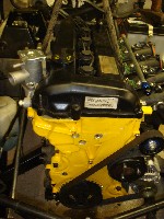
At this point the cam cover was screwed on, a dab of sealant (Ford Part No. WSE-M4G323-A6 or Loctite 30684, 30509 or 30507) having been added to the top of the interface between the timing-chain cover and the block. There was a superfluous hole in the cam cover where the camshaft position sensor should have been and I'd been racking my brains for a way to fill it for some time. A cork had been about my best idea so far. I put the problem to JH.
"Why not use a camshaft position sensor?" he replied. I muttered something about "out of the mouth of very babes and sucklings" but was secretly impressed. However, he then spoilt it by launching into a diatribe about how bleedin' useless these supposedly educated theoreticians are. A CPS was obtained from a fine gentleman named James (an ex-Sevener) who had bought all the goodies from the chap I got my engine from for an Elise conversion and who was also very helpful on the subject of the plumbing.
The excess material near the top of the timing chain cover had been milled off. We missed something here: because of the contours of the cover, the tendency is to mill at a bit of an angle, but you need to ensure that the milled surface is parallel to the mating face of the cover otherwise the three bolts in the milled area are forced to seat on an inclined surface. I had to take a die-grinder to the seats. Removing the Al alloy was not a problem, but getting through the paint was. To explain, I'd left JH's at about 9.00 one evening and had taken the cover home with me to paint it prior to fitting it the next day. I got home and ran a nice warm bath. I then put the cover in it (I hope, manly reader, that you didn't think the bath was for me - such girlie indulgences are not my style) before steam cleaning it. I made a mental note to clean the bath before the missus got back, assembled wine, brush and paint and set about my task. It has to be said that the first coat didn't go on terribly well - in some places the paint was thick, in some virtually transparent, and in others very streaky. Never mind, I thought, a second coat will sort that out. It was at this point that I made a strategic error. I should have waited for the first coat to dry before applying the second. However, it was a Friday evening, the hours on the clock were increasing, and the level in the wine bottle was decreasing. Added to which, I need my eight hours. Of course, none of this carried any weight at all with JH when he saw the cover the following morning. The next ten minutes were a mixture of hearty laughter and cutting abuse, concluding in, inevitably, a photograph so that he could cheer himself up in years to come. To be fair, I myself had difficulty in deciding whether it resembled more closely an alloy cover that had been painted yellow or a banana skin that had been galvanised.

With the timing cover on, the crank pulley (Part No. 1S7G6316BC, Finis code 1119175) was fitted, complete with diamond-studded washer (bling, bling) - for my relatively modest engine, it was not deemed necessary to key the crank. The crankshaft was positioned at TDC using, unsurprisingly, the TDC locator and then locked there with a flywheel locking tool skilfully fabricated by JH from a bit of studding, some rusty old steel and some sparrow poo. In my dictionary of engine building, cleanliness appears next to godliness; in JH's dictionary, it appears next to the entry for rust (noun, see entry under 'Aids to running in an engine'). I went to clean the sparrow poo off, but John stopped me,
"That's not sparrow poo, that's the welding holding it all together."
"Ah", I said, ... and tripped over his bloody engine stand.
The pulley was put in position, using the locating holes in the pulley and the timing chain cover and an M6 bolt, the TDC locator was then removed (to ensure it wouldn't be the thing stopping the crankshaft from turning when the pulley was bolted up), and then the pulley bolted up with the strain being taken by the JH locking tool (now painted a delightful battleship grey). The pulley having been bolted on (what a fine thing the ablative absolute is), the timing was set.
The cam timing was checked and adjusted with a dial gauge on a magnetic stand. The magnetic stand coupled with the alloy head gave JH another chance to produce a rusty old bit of steel like a conjuror taking a rabbit from a hat and scatter debris over my nice clean engine. However, despite his being fast on the draw, I was ready for him this time and sprang to the defence of my engine, determined to sell my life dearly if necessary. Seeing my resolve, JH relented and went off to do some polishing. Ten minutes later, we were adjusting the timing - lift at TDC 40 thou for the inlet and 56 thou for the exhaust.
With this done, the water pump, its pulley and the idler pulley were fitted and the belt added. The route followed by the belt can be seen below.

At this point the cam cover was screwed on, a dab of sealant (Ford Part No. WSE-M4G323-A6 or Loctite 30684, 30509 or 30507) having been added to the top of the interface between the timing-chain cover and the block. There was a superfluous hole in the cam cover where the camshaft position sensor should have been and I'd been racking my brains for a way to fill it for some time. A cork had been about my best idea so far. I put the problem to JH.
"Why not use a camshaft position sensor?" he replied. I muttered something about "out of the mouth of very babes and sucklings" but was secretly impressed. However, he then spoilt it by launching into a diatribe about how bleedin' useless these supposedly educated theoreticians are. A CPS was obtained from a fine gentleman named James (an ex-Sevener) who had bought all the goodies from the chap I got my engine from for an Elise conversion and who was also very helpful on the subject of the plumbing.
Fitting of the Raceline water rail required a bit of die-grinding at a few points on the head. My only remark here is that the thickness of the gasket is not insignificant so either trial fit with the gasket in place or allow a bit extra for it. Statement of the bleedin' obvious, I know, but I didn't think of it. The existing water temperature sensors fitted straight into the Raceline water rail. With the water rail on, the coil pack could be fitted.
If at all possible, try to arrange to build your engine in the same workshop as that in which somebody else is building a similar engine. This approach worked excellently for me. If ever I found I was missing a part, I simply called JH surreptitiously on my mobile, waited for him to leave the workshop to answer the telephone, and then whipped whatever I needed from his boxes of bits or straight from his engine. As a system, I don't see how it could be improved upon. And it saved me ££££s.
Next the crankshaft oil seal, spigot bearing, flywheel and clutch went on, using John's old bit of gearbox input shaft to align everything. A frequently used accessory - well, I assume it must have been as it wasn't covered in rust. The oil seal comes with a nifty fitting device and was simply pushed on and bolted in place.
Fitting of the starter motor and alternator was straightforward, though it should be remembered that the Raceline alternator assembly requires its own earth to the engine or the body - it's a lot easier to do this with the engine out of the car than in it (though you'd be amazed how useful the redundant K series exhaust hole is).
The crank position sensor (Part No. F1129988) is attached using a little plastic alignment tool that comes with it.
A thermostat housing was also obtained from James mentioned above. The housings for the mechanical and electrical thermostats both fit. The thermostat itself was removed as the Raceline water rail houses the thermostat. The steel pipe just above the housing was blanked off as I would not be using it.
The Raceline oil filter housing was used with the notorious Caterham oil pressure sender (the lip on the sender does foul slightly on the lip on the filter, but they will both go on satisfactorily with a hint of a soupcon of a suggestion of force).
[Update - During the rolling road session, it was noticed that the oil pressure was somewhat lower than ideal. A bit of research suggested that a relief valve in the oil filter itself might be responsible and so the oil filter was changed (suitable filters without the relief valve are, amongst others, Halfords HOF203, Champion C103 and Fram PH966B). This appeared to improve things slightly, but the pressure reading was still erratic and generally too low for true comfort. Brent Chiswick, who had originally highlighted the issue of the relief valve in the filter, was kind enough to spare some time for a chat. This, coupled with more research and the discovery of a post by Rob Walker which indicated that the Caterham sender strongly objected to the high initial pressures generated in Duratecs, suggested that the sender might be at fault. Rather than persist with the Caterham sender, I took a gamble and ordered a Racetech sender (Part No. RP-AST-OS) and suitable adaptor (Part No. ADP-M12X15A) from Merlin Motorsport. Of course, I didn't know whether that sender was compatible with the Caterham gauge. However, having found out that the gauges are just ammeters, I simply measured the resistance of a known good Caterham sender and my Racetech one under no pressure (for I like to be relaxed when doing these things). The resistances were 310 and 306 Ω respectively and so I was reasonably confident that I was getting an accurate reading, at least at the low end of the scale where it matters. Satisfactory is now what the oil pressure isn't anything else but. An added bonus is that the Racetech sender is slightly narrower and so doesn't foul on the oil filter (and it's also 12 p cheaper than the Caterham one (including the adapter which is, of course, a one-off purchase)).]
Fitting of the Jenvey throttle bodies (45 mm) was fairly straightforward, though for some reason one of the mounting holes in the cylinder head is larger than the others and not threaded. I reckon the chaps at Mazda did it like that to wind up the Ford people. And I'm sure that's also why, if you shine a torch down the hole, you can see the numbers 071241 (I shall leave it as an exercise for the reader (don't whinge - I've been doing all the work so far) to determine the significance of those numbers). Anyway, back to the hole. This means you've got to tap the hole to M10 or helicoil it to M8. If you do the former, you can either drill out the mounting hole in the TB to 10 mm or you can get some fine fellow to make up a stud that is M10 at one end and M8 at the other. In my case, JH kindly undertook the task of making up the stud. A couple of days later, JH proudly presented it to me. Unfortunately, I'd neglected to specify that I'd have preferred it to be circular in cross-section and JH, with immense skill (or because he has the only lathe in the world that can do it), had defaulted to oval. I cursed myself, both for my earlier negligence and for the fact that all my oval nuts were in a drawer at home. All was not lost though. By starting with some oval bar, JH was able to trick his lathe into turning out a circular stud and progress resumed. (Though to this day he maintains that he simply followed my instructions.)
My injectors would be going in the mounting holes in the head so the injector holes in the TBs were blanked off with little discs of aluminium.
With the TBs on, the necessary holes were cut in a blank (I couldn't track down a pre-drilled one) base plate (Demon Tweeks Part No. C6006). A template for doing this is here - if you print it out at 100 per cent, it should be spot on, but I suggest checking it against the TBs first - printers seem to do all sorts of strange things (and I'm not just talking about the electronic kind). A hole is also needed for the air temperature sensor.

Despite immense pressure and considerable abuse from a number of people, I was determined not to have to cut a hole in the bonnet. With no disrespect whatsoever to those who have cut holes in their bonnets, I really don't like how it looks - call me old fashioned (and many have called me far worse), but in my opinion sponge should only be seen in the company of a loofer and a rubber duck. I therefore used 45 mm trumpets and a relatively short air filter (Demon Tweeks Part No. C602D). With this arrangement, there is 20 mm between the end of the trumpet and the inside of the filter - I remember reading somewhere that the recommended minimum is ¾ inch (19 mm) so everything is tickety boo.
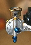
I got hold of some second-hand injectors from Pistonheads - they were green Weber IW031 330 cc/min high-impedance (note that - it's important - the Emerald needs high-impedance (greater than 12 Ω) injectors) top-feed injectors. The required flow rate was estimated using the tool provided by RC Engineering. There's also a good deal of useful information about injectors here. With hindsight, I'd probably have bought new injectors as, by the time I'd replaced the O rings, I'm not sure I saved much over the good deals that are available from Burton , Cosworth, SBD and others. The fuel rail was bought from SBD (Part No. TP3-DURA-JIC-6). This was chosen at it was one of the few I could find with both an inlet and an outlet, which was the arrangement we wanted, and which therefore wouldn't need a hole drilled and a connection brazed on. In this way, the fuel rail was plumbed in series with an adjustable fuel pressure regulator (Demon Tweeks Part No. FSE AIR006), with a gauge (to distract the eye from the 'orrible plastic standard cam cover) (Demon Tweeks Part No. FSE FPG002), to the fuel return pipe. -6 JIC fittings, with the necessary adaptors (the thread on the fuel supply where it emerges from the Seven transmission tunnel is M14 × 1.5 male), and 6 mm internal diameter black-plastic-coated aluminium pipe (in preference to the braided pipe favoured by many) were used throughout. The bits were obtained from the helpful chaps at Merlin Motorsport and the pipe was shaped using a manual pipe-bending tool from Cromwell tools.
I'm sure we did do other things before installing the engine, but I can't remember what they were so they can't have been that important.
Oh, in the words of Blockbuster, please rewind: there was one thing - the bell housing and gearbox assembly. Owing to an innate preference for cable-operated clutches over hydraulic ones (and because I'm incapable of bleeding anything hydraulic without covering everything within a 20 feet radius with brake fluid - it used only to be about 4 feet, but those pressurised Easy-bleed kits have really increased my range and ability to devastate (God help us if George Dubblya ever gets hold of one)), I was keen to have a cable-operated clutch. Derision and censure followed: "No chance" and "Why re-invent the wheel?" seemed to be the general consensus of the sceptics. I pointed out that I was simply reverting to the wheel that was around before somebody re-invented the hydraulic version of it. Unabashed, I posted a thread on TechTalk and Ammo of RaceCo reported that he would have a bell housing for a cable clutch available shortly. "Ha", I exclaimed to the sceptics, and I meant it to sting.
As for the gearbox, an E7 2.8 sporting close gearbox with a 2.66 ratio for first gear and a 0.82 ratio for fifth gear, along with a short input shaft (which allows the engine to be mounted 18 mm further back in the chassis apparently), was ordered from BGH. I picked up my gearbox and another one six weeks later, one in the passenger footwell and one in the boot. Much to the immense amusement of JH, I'd put the latter on top of a can of Tyreweld and so was greeted by a large amount of rubbery foam when I opened the boot. When JH finally stopped shaking with laughter, the old wotnot actually went to the trouble of taking a photograph of my misfortune. I watched him walk into the workshop, hoping he'd trip over his engine stand. He didn't. He tripped over a jack instead.
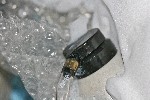
The bell housing was trial-mounted to the engine before installation. The only minor problem was that some of the sump casting had to be ground off as it overlapped the hole through which the clutch cable would pass. Also, the bell housing had been intended for use by Mr Ford on one of his rally cars. For that application, they like to be able to change the gearbox without removing the engine and so the housing and gearbox are held together by bolts from the back that pass through the gearbox casing into threaded holes in the bell housing. This simply meant that it was necessary to drill out the holes slightly to fit it in the conventional fashion.

I'm sure we did do other things before installing the engine, but I can't remember what they were so they can't have been that important.
Oh, in the words of Blockbuster, please rewind: there was one thing - the bell housing and gearbox assembly. Owing to an innate preference for cable-operated clutches over hydraulic ones (and because I'm incapable of bleeding anything hydraulic without covering everything within a 20 feet radius with brake fluid - it used only to be about 4 feet, but those pressurised Easy-bleed kits have really increased my range and ability to devastate (God help us if George Dubblya ever gets hold of one)), I was keen to have a cable-operated clutch. Derision and censure followed: "No chance" and "Why re-invent the wheel?" seemed to be the general consensus of the sceptics. I pointed out that I was simply reverting to the wheel that was around before somebody re-invented the hydraulic version of it. Unabashed, I posted a thread on TechTalk and Ammo of RaceCo reported that he would have a bell housing for a cable clutch available shortly. "Ha", I exclaimed to the sceptics, and I meant it to sting.
As for the gearbox, an E7 2.8 sporting close gearbox with a 2.66 ratio for first gear and a 0.82 ratio for fifth gear, along with a short input shaft (which allows the engine to be mounted 18 mm further back in the chassis apparently), was ordered from BGH. I picked up my gearbox and another one six weeks later, one in the passenger footwell and one in the boot. Much to the immense amusement of JH, I'd put the latter on top of a can of Tyreweld and so was greeted by a large amount of rubbery foam when I opened the boot. When JH finally stopped shaking with laughter, the old wotnot actually went to the trouble of taking a photograph of my misfortune. I watched him walk into the workshop, hoping he'd trip over his engine stand. He didn't. He tripped over a jack instead.

The bell housing was trial-mounted to the engine before installation. The only minor problem was that some of the sump casting had to be ground off as it overlapped the hole through which the clutch cable would pass. Also, the bell housing had been intended for use by Mr Ford on one of his rally cars. For that application, they like to be able to change the gearbox without removing the engine and so the housing and gearbox are held together by bolts from the back that pass through the gearbox casing into threaded holes in the bell housing. This simply meant that it was necessary to drill out the holes slightly to fit it in the conventional fashion.
The great day dawned bright and fair. At least I assume it did - at the time, like all right-thinking Englishmen, I was snugly tucked up between the sheets (well, between the sheet and the 10.5 tog continental microfibre duvet to be exact, but you get my drift, as the continent said).
A drive over to John's in the rain and we were ready to go. There are numerous accounts of the removal of an engine from a Seven that are far better written and far more accurate than one by me would ever be so I'll skip that bit and press on before your attention wanders. Suffice to say that by lunchtime the engine was out and the modifications to the footwells to accommodate the bell housing could begin. In my case, owing to the cable-clutch bell housing, slight modification of the driver's side footwell as well as the passenger's was required.
A drive over to John's in the rain and we were ready to go. There are numerous accounts of the removal of an engine from a Seven that are far better written and far more accurate than one by me would ever be so I'll skip that bit and press on before your attention wanders. Suffice to say that by lunchtime the engine was out and the modifications to the footwells to accommodate the bell housing could begin. In my case, owing to the cable-clutch bell housing, slight modification of the driver's side footwell as well as the passenger's was required.
In order to maintain the structural integrity of the chassis and to avoid any unwanted side-effects on the handling of the car it is imperative that the modifications are carried out with the utmost care and precision and with the correct tools. In order to leave the reader in no doubt, I've photographed the specialist tools that are required and they can be seen here.
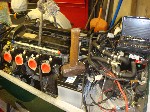
Once you've measured and marked everything up - we used lasers that had been calibrated for us by NASA and a sub-atomic electron hypermarker (Staples catalogue, Page 74) - grab the footwell modification tool firmly in your dominant hand. Then, as exemplified in the picture of the author below, keeping the head steady and the weight on the balls of the feet, and making sure that you don't over-rotate on the back-swing, give the footwell an almighty thwack. Do this three further times and see if the bell housing will fit. Repeat as necessary. Actually, this was all that was necessary on the driver's side; on the passenger side it was also necessary to drill out the rivets on the sloping section and cut along the corner of the front panel (else the flange for the rivets prevents it from bending - I'll admit it: on this occasion you were absolutely right John) before administering the above treatment. Once the required clearance had been achieved, sealant was applied and the panels drilled and riveted back together.


Once you've measured and marked everything up - we used lasers that had been calibrated for us by NASA and a sub-atomic electron hypermarker (Staples catalogue, Page 74) - grab the footwell modification tool firmly in your dominant hand. Then, as exemplified in the picture of the author below, keeping the head steady and the weight on the balls of the feet, and making sure that you don't over-rotate on the back-swing, give the footwell an almighty thwack. Do this three further times and see if the bell housing will fit. Repeat as necessary. Actually, this was all that was necessary on the driver's side; on the passenger side it was also necessary to drill out the rivets on the sloping section and cut along the corner of the front panel (else the flange for the rivets prevents it from bending - I'll admit it: on this occasion you were absolutely right John) before administering the above treatment. Once the required clearance had been achieved, sealant was applied and the panels drilled and riveted back together.

At this stage, the coolant expansion tank was removed as it would not be required, as was the bracket for the windscreen washer bottle - left where it was, adjacent to where the new exhaust primaries would be, it would have been ideal for de-icing in winter, but the thought of squirting exhaust-heated water towards my face was one that I didn't relish.
The gearbox and bell housing assembly was installed first (now's the time to put the gearbox oil in) and then the engine was lowered in (complete with TBs - as they're at the top, we figured that there wasn't much they could foul on and so they were attached prior to installation). After a bit of jiggling and poking, JH and I stopped messing about and went back to installing the engine. Working like a well-choreographed team (Laurel and Hardy spring to mind), the engine was soon mated to the bell housing and we stopped for lunch feeling like kings among men. As generally happens on these occasions when you are going to cop it in the quiet evenfall, the day had started extremely well. We returned from lunch and I crawled under the car to torque up the bell-housing-to-engine bolts. My arm brushed against the clutch release arm. "Funny," I thought, "funny". Having finished my Dudley Moore impersonation, I investigated further.
"John, shouldn't the clutch release arm be tight rather than floppy? It's flapping about like a cormorant in an oil slick" (for we speak to each other like that when we're alone).
He agreed. In an abiblical manner, the engine, which had descended like an angel, now rose again like Satan and we pawed over it like Holmes and Watson (you can decide who's which). Having measured footprints and smelt cigarette ash, we deduced that the receptionist at the shop where the bell housing had been cast was a 5' 6" blonde who smoked twenty Camel cigarettes a day and collected South American stamps. This was interesting, but it was getting us nowhere.
"John, this is interesting, but it's getting us nowhere", I said, for there are no secrets between us.
He agreed. That was twice in less than 30 minutes. Something was definitely wrong.
After a bit more measuring, it was found that the clutch release bearing needed to be 18 mm further forwards. (Having spoken to Ammo, it turned out that the clutch cover that I was using was different to that for which the bell housing had been designed.) Various suggestions were examined and rejected. Finally it was decided that we would weld two inverted pieces of 18 mm high L-section steel to the face of the release arm along the edges of the hole through which the gearbox shaft passed and mount the CRB on those. This was duly done and, mirabile dictu, it worked.


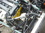
On the recommendation of Simon Bell, I used three existing Seven hoses (Part Nos 594-5, 594-3 and 73154) along with a dose of bling consisting of a 3" and two 12" × 32 mm connecting pipes from Demon Tweeks (Part Nos AHF093 and AHF095) (I think one of the 12" could have been replaced with a 6"). This gave the arrangement that can be seen below (please excuse the state of the wiring (and everything else) - it's still a work in progress).
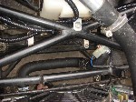
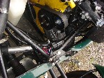
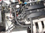
And there is a schematic here.
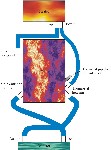


And there is a schematic here.

With the engine in situ, the fuel system could be plumbed in. The fuel pressure regulator was simply mounted on the block using a piece of steel sheet cut to size. The tubing was bent and cut to length mainly by trial and error, but also by creating a template using some malleable wire - I'd bought 4 metres of tube knowing that I'd be unlikely to get it right first time (and I was right - I didn't).
The throttle cable was routed along the exhaust side of the engine, left at the water rail main outlet, left again at the alternator and then back along the engine under the TBs, at which point we needed something to mount it to. Forward JH with yet another rusty old piece of steel. Caught off guard and too weak to resist, I left him to it. He returned a while later and I saw that he had surpassed himself - the rust had vanished like the dew off a rose and he'd even drilled some lightening holes for that aerospace touch and painted it that fashionable battleship grey. It was basically a T shape, the bottom end of which had been bent through 90° and drilled and slotted, and it would be attached to the TBs using the ends of the lower inner trumpet bolts. The leg of the T needs to be sufficiently long (> 6") to keep the variation in the angle of the cable as the throttle is opened and closed to a minimum. The throttle cable used was from a Shimano bike brake cable set from Halfords (Part No. 404764). The threaded bit of sleeve that was required was cut from the old throttle cable.
I went to install the clutch cable. The existing cable was a few inches too short because the point it needs to reach is somewhat lower down than for the K series arrangement (as JH pointed out, this means that if you leave out the rubber boot the clutch is nicely water-cooled). Lenco in Tunbridge Wells kindly let me rummage through their racks of cables and I soon found a suitable one (QH Part No. QCC1063). The next problem was that using the existing hole in the pedal box meant that part of the cable was clearly going to occupy space required for other purposes, namely No. 4 exhaust primary. So, after some deliberation, the relevant section of the front face of the pedal box was removed and re-attached slightly lower and to the left using some spare sparrow poo.
JH had obtained some second-hand Raceline primaries and a 4-into-1 collector for me and a new Techcraft silencer would be used. He had also, in my absence thankfully, for I am a sensitive man, cut a hole for the exhaust in the side skin. The primaries were lagged with Cooltek wrap from Proven Products, partly because I'm a cheapskate and this was indeed cheap and partly because I confused Cooltek and Thermotec. I ignored JH's advice to use jubilee clips rather than the steel ties that you can get. Humble pie is improved by a liberal dollop of custard. He was right - the steel ties don't work; they also creep up when you aren't looking and lacerate any exposed flesh.
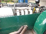
The Techcraft silencer is very shiny, really very shiny indeed. Whether more or less shiny than the alternatives, I couldn't say, but certainly well up there. Unfortunately, what it gains in shininess, it loses in lack of mounting brackets. A visit to JH's local blacksmith where a stainless steel stud was welded to the underside of the tail pipe was therefore necessary. From here a steel bar, via a bobbin, attached the exhaust to the car using the harness attachment hole (which was drilled through from the inside and then enlarged slightly from the outside). We, well mainly JH really, weren't too happy about the lack of support fore of the silencer and the plan is to visit Dave at Powerspeed and ask him to make up a 4-into-2-into-1 collector with a bracket (the relatively short length of the silencer means that there's plenty of room to do this).
[Update - putting the bobbin at the chassis end of the bar meant there was too high a bending load on the stud on the tail pipe (which I should have twigged) with the result that the material around the weld has cracked. The bobbin is now attached to the silencer (which is awfully shiny - have I mentioned that?) and the other end of the bar is rigidly mounted to the chassis. This seems to be a far better arrangement.]
Grateful thanks are due to Rob Walker for his help with the wiring.
This was the bit I'd been dreading. Despite having been a diligent student of physics during my formative y's, those damned electrons seem to me to have minds of their own and to head wheresoever they wish, with complete disregard for any instruction to the contrary.
To prepare the little grey cells for some strenuous activity, I wrapped a cold towel around my head and began to assemble the facts before me prior to a logical assault on the problem. I stiffened the sinews and summoned up the blood, determined to make progress. I made some progress, but of the wrong kind and quickly becoming more rapid as I tripped over John's engine stand. I took the towel off my head. It really hadn't helped.
To prepare the little grey cells for some strenuous activity, I wrapped a cold towel around my head and began to assemble the facts before me prior to a logical assault on the problem. I stiffened the sinews and summoned up the blood, determined to make progress. I made some progress, but of the wrong kind and quickly becoming more rapid as I tripped over John's engine stand. I took the towel off my head. It really hadn't helped.

